A solar panel wiring diagram is a visual guide that illustrates the connections between solar panels‚ inverters‚ batteries‚ and other components. It ensures safe and efficient installation‚ helping users avoid electrical hazards and optimize energy output.
Importance and Applications of Solar Panel Wiring Diagrams

Solar panel wiring diagrams are essential for ensuring the safe and efficient installation of solar power systems. They serve as a blueprint‚ guiding installers and DIY enthusiasts through the complex process of connecting solar panels‚ inverters‚ batteries‚ and other components. These diagrams are critical for preventing electrical hazards‚ such as short circuits or overloads‚ and ensuring compliance with local electrical codes. Their universal language makes them accessible to professionals worldwide‚ facilitating collaboration and troubleshooting. Applications range from residential and commercial installations to RVs and off-grid systems. They are also invaluable for planning system upgrades‚ diagnosing faults‚ and educating newcomers to solar technology. By providing a clear visual representation‚ solar wiring diagrams simplify the integration of renewable energy solutions‚ making them indispensable for both novice and experienced users. Their role in promoting sustainability and energy independence underscores their significance in the growing renewable energy sector.
Key Components of a Solar Panel Wiring Diagram
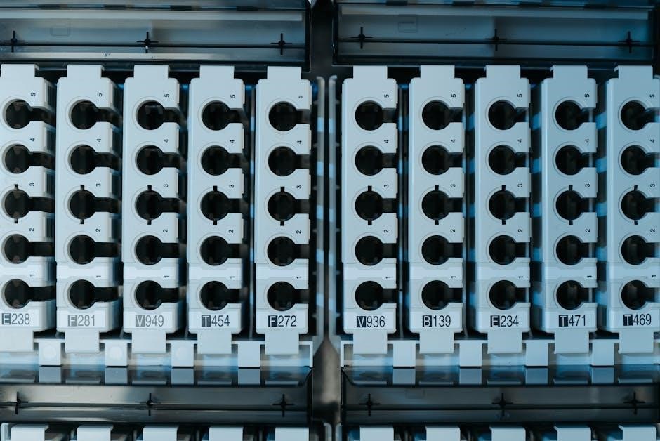
A solar panel wiring diagram typically includes several key components that ensure the system functions safely and efficiently. These components are represented visually to guide installers and users. First‚ solar panels are shown as the energy source‚ connected in series or parallel. The inverter is depicted to illustrate how it converts DC power to AC. Batteries are included if the system includes energy storage. The charge controller is essential for regulating power flow to the batteries. Fuses and circuit breakers are highlighted to show overload protection. Connectors and wires are detailed to specify sizes and connections. A combiner box may be included for multiple panels. The grounding system is emphasized for safety. These components are interconnected logically‚ with arrows indicating the direction of current flow. Understanding these elements is crucial for designing and troubleshooting solar systems effectively. They ensure compliance with electrical standards and promote a reliable energy supply. Proper interpretation of these components is vital for both installation and maintenance.
Types of Solar Panel Wiring Diagrams
Solar panel wiring diagrams are categorized into series‚ parallel‚ and combination configurations. Series diagrams prioritize higher voltage‚ while parallel diagrams focus on higher current. Combination diagrams offer flexibility for complex systems‚ balancing voltage and current needs.
Series Circuit Wiring Diagrams
A series circuit wiring diagram illustrates how solar panels are connected end-to-end to increase the system’s total voltage while maintaining the same current. This configuration is ideal for applications where higher voltage is required‚ such as charging batteries or connecting to inverters with specific voltage requirements. In a series connection‚ the positive terminal of one panel is connected to the negative terminal of the next‚ creating a cumulative voltage output. This setup minimizes the number of connections and reduces wiring complexity. However‚ it can be less flexible if one panel underperforms‚ as it affects the entire circuit. Series diagrams are commonly used in off-grid systems or when maximizing voltage for charge controllers or inverters. They are straightforward to design but require careful planning to ensure compatibility between components. Properly following a series wiring diagram ensures efficient energy transfer and system reliability‚ making it a popular choice for many solar installations.
Parallel Circuit Wiring Diagrams
A parallel circuit wiring diagram demonstrates how solar panels are connected positively to positively and negatively to negatively‚ maintaining the same voltage while increasing the current. This configuration is ideal for systems requiring higher current output‚ such as grid-tie setups or battery charging systems with specific power needs. In parallel connections‚ each panel operates independently‚ reducing the impact of shading or underperformance on individual panels. This setup is more flexible‚ allowing for easier addition of panels or replacement of faulty ones. However‚ it may require additional components like combiner boxes to manage multiple connections safely. Parallel diagrams are widely used in residential and commercial solar installations where consistent energy output is crucial. They offer better redundancy and scalability compared to series connections‚ making them a preferred choice for larger or more complex systems. Properly following a parallel wiring diagram ensures optimal performance‚ safety‚ and reliability in solar energy systems.
Combination Circuit Wiring Diagrams
A combination circuit wiring diagram integrates both series and parallel configurations‚ offering flexibility for complex solar panel setups. This design allows for balancing voltage and current requirements‚ making it ideal for systems with varying energy demands. By organizing panels into sub-arrays connected in series and then linking these arrays in parallel‚ combination diagrams provide scalability and customization. This setup is particularly useful for large-scale installations or systems requiring precise voltage and current matching. It enables users to maximize energy output while accommodating different panel ratings or orientations. Combination diagrams are essential for optimizing performance in both residential and commercial solar systems‚ ensuring efficient energy harvest and system reliability. They also simplify troubleshooting by isolating issues within specific sub-arrays. Properly following a combination wiring diagram ensures a balanced and efficient solar energy system tailored to specific energy needs.
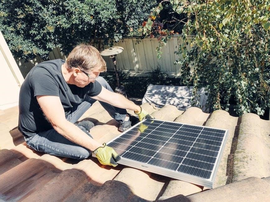
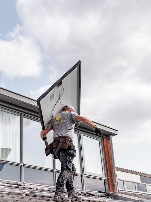
Installation Steps for Solar Panel Wiring
Installing solar panel wiring requires careful planning and adherence to safety guidelines. Begin by reviewing the solar panel wiring diagram to understand the connections between panels‚ inverters‚ batteries‚ and electrical components. Ensure all necessary tools and materials‚ such as solar panels‚ mounting hardware‚ and wiring‚ are available. Mount the solar panels securely on the roof or ground‚ following the manufacturer’s instructions; Connect the panels in the desired configuration (series‚ parallel‚ or combination) as per the wiring diagram. Install the inverter and combiner box‚ ensuring proper grounding for safety. Run the wiring from the panels to the inverter and then to the electrical system or battery bank. Use appropriate wire sizes and fuses to prevent overcurrent issues. Test the system to ensure all components function correctly and energy flows as intended. Finally‚ connect the system to the grid or standalone power source‚ following local electrical codes. Always consult a professional if unsure about any step to avoid hazards and ensure compliance with safety standards.
Troubleshooting Common Issues Using Wiring Diagrams
Solar panel wiring diagrams are invaluable for diagnosing and resolving common issues in solar systems. Begin by identifying symptoms such as reduced power output‚ flickering lights‚ or system shutdowns. Use the wiring diagram to trace connections and isolate faulty components. Common issues include loose connections‚ short circuits‚ or open circuits. Check for signs of wear‚ corrosion‚ or damage in wires and connectors. Verify that all components‚ such as inverters and charge controllers‚ are functioning correctly. Use a multimeter to measure voltage and current at key points‚ comparing readings to the expected values shown in the wiring diagram. Ground faults or improper polarity can also cause malfunctions‚ so ensure all grounding points are secure. If issues persist‚ consult the manufacturer’s troubleshooting guide or seek professional assistance. Regular maintenance and reference to the wiring diagram can prevent many problems‚ ensuring optimal system performance and safety. Always prioritize safety by disconnecting power before inspecting or repairing components.

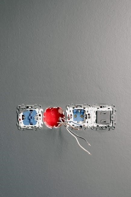
Safety Considerations When Using Solar Panel Wiring Diagrams
Ensuring safety is paramount when working with solar panel wiring diagrams. Always disconnect the system from the power source before performing any maintenance or repairs. Wear appropriate protective gear‚ such as insulated gloves and safety glasses‚ to prevent electrical shocks or injuries. Follow the wiring diagram precisely to avoid misconnections that could lead to short circuits or fires. Grounding is critical; ensure all components are properly grounded to prevent electrical hazards. Never touch electrical components without verifying they are de-energized. Keep the area clear of flammable materials and avoid working in wet conditions. If unsure about any part of the process‚ consult a licensed electrician or the system’s manual. Regularly inspect wires and connections for signs of wear or damage‚ addressing issues promptly. Adhere to local electrical codes and standards to ensure compliance and safety. Remember‚ a well-understood wiring diagram is not only a tool for installation but also a guide for safe system operation and maintenance. Always prioritize caution to protect yourself and the solar system from potential risks.
Leave a Reply